Toyota Venza: Washer Motor(for Rear Side)
Components
COMPONENTS
ILLUSTRATION

Removal
REMOVAL
PROCEDURE
1. REMOVE FRONT WHEEL RH
2. REMOVE FRONT FENDER OUTSIDE MOULDING RH
HINT:
Use the same procedure for the RH side and LH side (See page
.gif) ).
).
3. REMOVE FRONT FENDER LINER RH
4. DRAIN WINDSHIELD WASHER FLUID
|
(a) Disconnect the washer hose from the rear washer motor and pump assembly, and drain the washer fluid. HINT: Use a container to collect the washer fluid. |
|

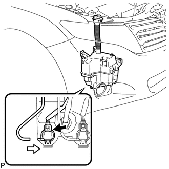
5. REMOVE REAR WASHER MOTOR AND PUMP ASSEMBLY
|
(a) Disconnect the connector. |
|

(b) Remove the rear washer motor and pump assembly.
HINT:
Use a container to collect the washer fluid.
Inspection
INSPECTION
PROCEDURE
1. INSPECT REAR WASHER MOTOR AND PUMP ASSEMBLY
(a) Remove the washer jar.
(b) Disconnect the rear washer motor and pump connector.
HINT:
The check should be performed with the rear washer motor and pump installed on the washer jar.
(c) Fill the washer jar with washer fluid.
|
(d) Connect a battery positive (+) lead to terminal 1 of the rear washer motor and pump, and a negative (-) lead to terminal 2. |
|

(e) Check that washer fluid flows from the washer jar.
OK:
Washer fluid flows from the washer jar.
If the result is not as specified, replace the rear washer motor and pump assembly.
Text in Illustration|
*1 |
Component without harness connected (Rear Washer Motor and Pump Assembly) |
Installation
INSTALLATION
PROCEDURE
1. INSTALL REAR WASHER MOTOR AND PUMP ASSEMBLY
|
(a) Install the rear washer motor and pump assembly. |
|
(b) Connect the connector.
(c) Connect the washer hose.
2. FILL WASHER JAR WITH WASHER FLUID
(a) Fill the washer jar with washer fluid.
3. INSTALL FRONT FENDER LINER RH
.gif)
4. INSTALL FRONT FENDER OUTSIDE MOULDING RH
HINT:
Use the same procedure for the RH side and LH side (See page
).
5. INSTALL FRONT WHEEL RH
 Washer Motor(for Front Side)
Components
COMPONENTS
ILLUSTRATION
Removal
REMOVAL
PROCEDURE
1. REMOVE FRONT WHEEL RH
2. REMOVE FRONT FENDER OUTSIDE MOULDING RH
HINT:
Use the same procedure for the RH side and LH side ...
 Washer Nozzle(for Front Side)
Components
COMPONENTS
ILLUSTRATION
On-vehicle Inspection
ON-VEHICLE INSPECTION
PROCEDURE
1. INSPECT FRONT WASHER NOZZLE SUB-ASSEMBLY
(a) With the engine running, check that the center str ...
Other materials about Toyota Venza:
Removal
REMOVAL
PROCEDURE
1. DISCONNECT CABLE FROM NEGATIVE BATTERY TERMINAL
CAUTION:
Wait at least 90 seconds after disconnecting the cable from the negative (-)
battery terminal to disable the SRS system.
NOTICE:
When disconnecting the cable, some systems ne ...
Components
COMPONENTS
ILLUSTRATION
ILLUSTRATION
ILLUSTRATION
ILLUSTRATION
ILLUSTRATION
ILLUSTRATION
ILLUSTRATION
...
Inspection
INSPECTION
PROCEDURE
1. INSPECT TIE ROD ASSEMBLY LH
(a) Secure the tie rod assembly LH in a vise.
(b) Install the nut to the stud bolt.
(c) Flip the ball joint back and forth 5 times.
(d) Set a to ...

0.153