Toyota Venza: Short to GND in Immobiliser System Power Source Circuit (B278A)
DESCRIPTION
This DTC is stored when the engine switch power source supply line is open or shorted.
|
DTC No. |
DTC Detection Condition |
Trouble Area |
|---|---|---|
|
B278A |
Engine switch power source supply line is open or shorted. |
|
WIRING DIAGRAM

CAUTION / NOTICE / HINT
NOTICE:
If the certification ECU (smart key ECU assembly) is replaced, register the key
(See page .gif) ).
).
PROCEDURE
|
1. |
CHECK DTC OUTPUT |
(a) Clear the DTCs (See page ).
(b) Recheck for DTCs (See page ).
OK:
DTC B278A is not output.
| OK | .gif) |
USE SIMULATION METHOD TO CHECK |
|
.gif)
|
2. |
CHECK HARNESS AND CONNECTOR (CERTIFICATION ECU - ENGINE SWITCH) |
(a) Disconnect the certification ECU (smart key ECU assembly) connector.
|
(b) Disconnect the engine switch connector. |
|
(c) Measure the resistance according to the value(s) in the table below.
Standard Resistance:
|
Tester Connection |
Condition |
Specified Condition |
|---|---|---|
|
D25-28 (VC5) - D13-14 (VC5) |
Always |
Below 1 Ω |
|
D25-36 (AGND) - D13-8 (AGND) |
Always |
Below 1 Ω |
|
D25-28 (VC5) - Body ground |
Always |
10 kΩ or higher |
|
D25-36 (AGND) - Body ground |
Always |
10 kΩ or higher |
|
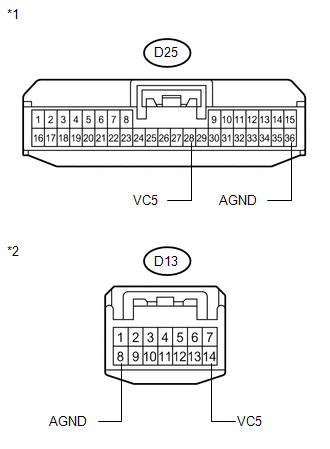
*1 |
Front view of wire harness connector (to Certification ECU (Smart Key ECU Assembly)) |
|
*2 |
Front view of wire harness connector (to Engine Switch) |
| NG | |
REPAIR OR REPLACE HARNESS OR CONNECTOR |
|
|
3. |
CHECK CERTIFICATION ECU (SMART KEY ECU ASSEMBLY) |
(a) Reconnect the certification ECU (smart key ECU assembly) connector.
(b) Reconnect the engine switch connector.
(c) Using an oscilloscope, check the waveform.

Waveform (Reference):
|
Item |
Content |
|---|---|
|
Tester Connection |
D25-28 (VC5) - D25-36 (AGND) |
|
Tool Setting |
2 V/DIV., 200 ms./DIV. |
|
Condition |
|
OK:
Waveform is output normally (see illustration)
|
Result |
Proceed to |
|---|---|
|
NG |
A |
|
OK (for 2GR-FE) |
B |
|
OK (for 1AR-FE) |
C |
|
*1 |
Component with harness connected (Certification ECU (Smart Key ECU Assembly)) |
|
*2 |
GND |
| A | |
REPLACE CERTIFICATION ECU (SMART KEY ECU ASSEMBLY) |
| B | |
REPLACE ENGINE SWITCH |
| C | |
REPLACE ENGINE SWITCH |
 Theft Deterrent System Communication Line High Fixation (B279A)
DESCRIPTION
If the communication line (EFIO - IMI) to the certification ECU (smart key ECU
assembly) is stuck high output (e.g. shorted to +B), the ECM stores this DTC.
DTC No.
...
 Engine Immobiliser System Malfunction (B2799)
DESCRIPTION
This DTC is stored when one of the following occurs: 1) the ECM detects an error
in its own communication with the certification ECU (smart key ECU assembly); 2)
the ECM detects an er ...
Other materials about Toyota Venza:
Horn Circuit
DESCRIPTION
When the theft deterrent system is switched from the armed state to the alarm
sounding state, the main body ECU (driver side junction block assembly) transmits
a signal to cause the horn to sound at intervals of 0.4 seconds.
WIRING DIAGRAM
...
Removal
REMOVAL
CAUTION / NOTICE / HINT
HINT:
Use the same procedure for the RH side and LH side.
The procedure listed below is for the LH side.
PROCEDURE
1. REMOVE REAR WHEEL
2. SEPARATE REAR SPEED SENSOR
(a) Remove the bolt and se ...
Performance Decline of Brake Function (C1441)
DESCRIPTION
The skid control ECU judges brake failure conditions have occurred based on the
signal from the brake pedal load sensing switch and master cylinder pressure sensor.
NOTICE:
Do not intentionally stop the engine when driving. Even when no malfun ...

0.1125