Toyota Venza: Power Source Control ECU Malfunction (B2782)
DESCRIPTION
The power management control ECU controls the power supply to activate the steering lock motor. This prevents the steering wheel from being locked while the vehicle is moving.
|
DTC No. |
DTC Detecting Condition |
Trouble Area |
|---|---|---|
|
B2782 |
Steering lock motor drive control circuit is defective. |
|
WIRING DIAGRAM

CAUTION / NOTICE / HINT
HINT:
After replacing the steering lock ECU (steering lock actuator assembly), confirm
the Initialization of the steering lock (See page
.gif) ).
).
PROCEDURE
|
1. |
INSPECT STEERING LOCK ECU (STEERING LOCK ACTUATOR ASSEMBLY) |
|
(a) Measure the voltage according to the value(s) in the table below. Standard Voltage:
HINT: The steering lock ECU and steering lock actuator assembly are supplied as a single unit. |
|
|
*1 |
Component with harness connected (Steering Lock ECU (Steering Lock Actuator Assembly)) |
| OK | .gif) |
REPLACE STEERING LOCK ECU (STEERING LOCK ACTUATOR ASSEMBLY) |
|
.gif)
|
2. |
CHECK HARNESS AND CONNECTOR (STEERING LOCK ECU - BODY GROUND) |
|
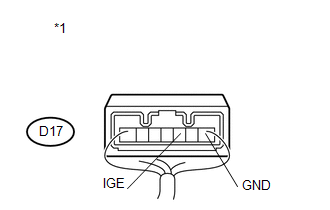
(a) Disconnect the D17 connector from the steering lock actuator assembly. |
|
.png)
(b) Measure the resistance according to the value(s) in the table below.
Standard Resistance:
|
Tester Connection |
Condition |
Specified Condition |
|---|---|---|
|
D17-1 (GND) - Body ground |
Always |
Below 1 Ω |
|
*1 |
Front view of wire harness connector (to Steering Lock ECU (Steering Lock Actuator Assembly)) |
| NG | |
REPAIR OR REPLACE HARNESS OR CONNECTOR |
|
|
3. |
CHECK HARNESS AND CONNECTOR (STEERING LOCK ECU - POWER MANAGEMENT CONTROL ECU) |
|
(a) Disconnect the D43 connector from the power management control ECU. |
|

(b) Measure the resistance according to the value(s) in the table below.
Standard Resistance:
|
Tester Connection |
Condition |
Specified Condition |
|---|---|---|
|
D17-3 (IGE) - D43-8 (SLR+) |
Always |
Below 1 Ω |
|
D17-3 (IGE) - Body ground |
Always |
10 kΩ or higher |
|
*1 |
Front view of wire harness connector (to Steering Lock ECU (Steering Lock Actuator Assembly)) |
|
*2 |
Front view of wire harness connector (to Power Management Control ECU) |
| OK | |
REPLACE POWER MANAGEMENT CONTROL ECU |
| NG | |
REPAIR OR REPLACE HARNESS OR CONNECTOR |
 Diagnostic Trouble Code Chart
DIAGNOSTIC TROUBLE CODE CHART
If a trouble code is displayed during the DTC check, check the parts listed for
that code in the table below and proceed to the appropriate page.
HINT:
The steering ...
 Open / Short in Steering Lock ECU (B2781)
DESCRIPTION
If the steering lock ECU (steering lock actuator assembly) determines that there
is a malfunction inside the ECU, it outputs this DTC. Diagnostic communication between
the steering lo ...
Other materials about Toyota Venza:
Rear Occupant Classification Sensor LH Circuit Malfunction (B1782)
DESCRIPTION
The rear occupant classification sensor LH circuit consists of the occupant classification
ECU and rear occupant classification sensor LH.
DTC B1782 is recorded when a malfunction is detected in the rear occupant classification
sensor LH circ ...
On-vehicle Inspection
ON-VEHICLE INSPECTION
CAUTION / NOTICE / HINT
CAUTION:
Be sure to follow the correct removal and installation procedures of the steering
pad.
PROCEDURE
1. INSPECT STEERING PAD (Vehicle not Involved in Collision)
(a) Perform a diagnostic system check (S ...
Fail-safe Chart
FAIL-SAFE CHART
1. FAIL-SAFE OPERATION
If there is a problem with sensor signals or actuator systems, the skid
control ECU prohibits power supply to the brake actuator assembly and informs
the ECM of VSC system malfunction.
The brake actuat ...

0.1304