Toyota Venza: Installation
INSTALLATION
PROCEDURE
1. INSTALL POWER OUTLET SOCKET COVER NO.1
|
(a) Engage the 2 claws to install the power point socket cover. |
|
.png)
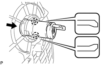
2. INSTALL POWER POINT SOCKET ASSEMBLY
|
(a) Engage the 2 claws to install the power point socket assembly as shown in the illustration. |
|
3. INSTALL CONSOLE BOX SUB-ASSEMBLY
.gif)
4. INSTALL POSITION INDICATOR HOUSING ASSEMBLY
5. INSTALL SHIFT LEVER KNOB SUB-ASSEMBLY
6. INSTALL LOWER INSTRUMENT PANEL SUB-ASSEMBLY
7. INSTALL NO. 2 INSTRUMENT PANEL UNDER COVER SUB-ASSEMBLY
8. INSTALL COWL SIDE TRIM SUB-ASSEMBLY RH
9. INSTALL FRONT DOOR SCUFF PLATE RH
10. INSTALL LOWER NO. 1 INSTRUMENT PANEL FINISH PANEL
11. INSTALL COWL SIDE TRIM SUB-ASSEMBLY LH
12. INSTALL FRONT DOOR SCUFF PLATE LH
13. INSTALL AIR CONDITIONING CONTROL ASSEMBLY
14. INSTALL CONSOLE BOX ASSEMBLY
15. INSTALL NO. 2 CONSOLE BOX CARPET
16. INSTALL UPPER CONSOLE PANEL SUB-ASSEMBLY (w/o Seat Heater System)
17. INSTALL UPPER CONSOLE PANEL SUB-ASSEMBLY (w/ Seat Heater System)
 Removal
REMOVAL
PROCEDURE
1. REMOVE UPPER CONSOLE PANEL SUB-ASSEMBLY (w/o Seat Heater System)
2. REMOVE UPPER CONSOLE PANEL SUB-ASSEMBLY (w/ Seat Heater System)
3. REMOVE NO. 2 CONSOLE BOX CARPET
...

Other materials about Toyota Venza:
Check CAN Bus Line for Short to +B
DESCRIPTION
There may be a short circuit between the CAN bus main wire and +B when no resistance
exists between terminals 6 (CANH) and 16 (BAT) or 14 (CANL) and 16 (BAT) of the
DLC3.
Symptom
Trouble Area
No resistan ...
Inspection
INSPECTION
PROCEDURE
1. INSPECT BRAKE VACUUM CHECK VALVE ASSEMBLY
(a) Check that there is ventilation from the booster to the engine, and
no ventilation from the engine to the booster.
If the results are not as specified, replace the brake ...
Installation
INSTALLATION
PROCEDURE
1. INSTALL BRAKE MASTER CYLINDER SUB-ASSEMBLY
NOTICE:
When install a new brake master cylinder sub-assembly, remove the protectors
from the piston and outlet ports.
(a) Install a new O-ring to the brake master cylinder sub-assembl ...

0.1179