Toyota Venza: Diagnosis Circuit
DESCRIPTION
This circuit is used to read the DTCs that are output from the transponder key ECU assembly with the Techstream.
WIRING DIAGRAM

CAUTION / NOTICE / HINT
NOTICE:
If the transponder key ECU assembly is replaced, register the key and ECU communication
ID (See page .gif) ).
).
PROCEDURE
|
1. |
CHECK HARNESS AND CONNECTOR (DLC3 - TRANSPONDER KEY ECU AND BODY GROUND) |
|
(a) Disconnect the transponder key ECU assembly connector. |
|
(b) Measure the resistance according to the value(s) in the table below.
Standard Resistance:
|
Tester Connection |
Condition |
Specified Condition |
|---|---|---|
|
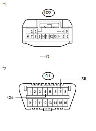
D22-9 (D) - D1-7 (SIL) |
Always |
Below 1 Ω |
|
D1-4 (CG) - Body ground |
Always |
Below 1 Ω |
|
D22-9 (D) - Body ground |
Always |
10 kΩ or higher |
|
D1-7 (SIL)- Body ground |
Always |
10 kΩ or higher |
|
*1 |
Front view of wire harness connector (to Transponder Key ECU Assembly) |
|
*2 |
Front view of wire harness connector (to DLC3) |
| OK | .gif) |
REPLACE TRANSPONDER KEY ECU ASSEMBLY |
| NG | |
REPAIR OR REPLACE HARNESS OR CONNECTOR |
 ECU Power Source Circuit
DESCRIPTION
This circuit provides power to operate the transponder key ECU assembly.
WIRING DIAGRAM
CAUTION / NOTICE / HINT
NOTICE:
If the transponder key ECU assembly is replaced, register the ...

Other materials about Toyota Venza:
Removal
REMOVAL
CAUTION / NOTICE / HINT
HINT:
Use the same procedure for the RH and LH sides.
The procedure described below is for the LH side.
PROCEDURE
1. PRECAUTION (for HID Headlight)
(See page )
NOTICE:
After turning the ignition switch ...
Torque Sensor Circuit Malfunction (C1511-C1514,C1517)
DESCRIPTION
The torque sensor converts the rotation torque input to the steering wheel into
an electrical signal and sends it to the power steering ECU. Based on this signal,
the ECU detects steering effort.
DTC No.
DTC Detection Co ...
Disassembly
DISASSEMBLY
CAUTION / NOTICE / HINT
HINT:
Use the same procedure for the RH side and the LH side.
The procedure listed below is for the LH side.
PROCEDURE
1. REMOVE REAR WHEEL
2. REMOVE REAR AXLE SHAFT NUT (for AWD)
NOTICE:
Perform th ...

0.1119