Toyota Venza: Camshaft Position Sensor
Components
COMPONENTS
ILLUSTRATION

Installation
INSTALLATION
PROCEDURE
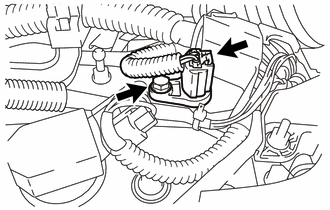
1. INSTALL CAMSHAFT POSITION SENSOR (for Exhaust Side)
(a) Apply a light coat of engine oil to the O-ring of the camshaft position sensor.
NOTICE:
If reusing the camshaft position sensor, be sure to inspect the O-ring.
(b) Install the camshaft position sensor to the cylinder head cover sub-assembly with the bolt.
Torque:
10 N·m {102 kgf·cm, 7 ft·lbf}
NOTICE:
- If the camshaft position sensor has been struck or dropped, replace it.
- Make sure that the O-ring is not cracked or moved out of place when installing the camshaft position sensor.
(c) Connect the camshaft position sensor connector.
2. INSTALL CAMSHAFT POSITION SENSOR (for Intake Side)
(a) Apply a light coat of engine oil to the O-ring of the camshaft position sensor.
NOTICE:
If reusing the camshaft position sensor, be sure to inspect the O-ring.
(b) Install the camshaft position sensor with the bolt.
Torque:
10 N·m {102 kgf·cm, 7 ft·lbf}
NOTICE:
- If the camshaft position sensor has been struck or dropped, replace it.
- Make sure that the O-ring is not cracked or moved out of place when installing the camshaft position sensor.
(c) Connect the camshaft position sensor connector.
3. INSPECT FOR OIL LEAK
4. INSTALL NO. 1 ENGINE COVER SUB-ASSEMBLY
.gif)
Removal
REMOVAL
PROCEDURE
1. REMOVE NO. 1 ENGINE COVER SUB-ASSEMBLY
.gif)
2. REMOVE CAMSHAFT POSITION SENSOR (for Exhaust Side)

(a) Disconnect the sensor connector.
(b) Remove the bolt and sensor.
3. REMOVE CAMSHAFT POSITION SENSOR (for Intake Side)
(a) Disconnect the sensor connector.
(b) Remove the bolt and sensor.
 Installation
INSTALLATION
PROCEDURE
1. INSTALL CAMSHAFT TIMING OIL CONTROL VALVE ASSEMBLY (for Exhaust Side)
(a) Apply a light coat of engine oil to a new O-ring, and install it
to the oil contro ...
 Crankshaft Position Sensor
Components
COMPONENTS
ILLUSTRATION
Removal
REMOVAL
PROCEDURE
1. REMOVE FRONT FENDER APRON SEAL RH
2. REMOVE CRANKSHAFT POSITION SENSOR
(a) Disconnect the sensor connector.
(b) Remo ...
Other materials about Toyota Venza:
Illumination Circuit
DESCRIPTION
Power is supplied to the radio and display receiver assembly and steering pad
switch assembly illumination when the light control switch is in the tail or head
position.
WIRING DIAGRAM
CAUTION / NOTICE / HINT
NOTICE:
The vehicle ...
Data Signal Circuit between Radio Receiver and Extension Module
DESCRIPTION
The stereo component tuner assembly sends the image data signal to the radio
and display receiver assembly via this circuit.
WIRING DIAGRAM
PROCEDURE
1.
CHECK NAVIGATION WIRE
(a) Remove the navigation wire ( ...
If the vehicle becomes stuck
Carry out the following procedures if the tires spin or the vehicle becomes
stuck in mud, dirt, or snow.
Stop the engine. Set the parking
brake and shift the shift lever in “P”.
Stop the engine. Set the parking
brake and shift the shift lever in †...

0.137