Toyota Venza: Solar Sensor
Components
COMPONENTS
ILLUSTRATION

On-vehicle Inspection
ON-VEHICLE INSPECTION
PROCEDURE
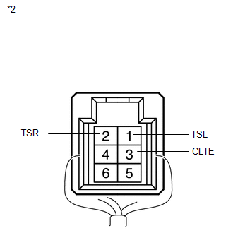
1. INSPECT SOLAR SENSOR
|
(a) Disconnect the solar sensor connector. |
|

(b) Measure the voltage according to the value(s) in the table below.
Standard Voltage:
|
Tester Connection |
Condition |
Specified Condition |
|---|---|---|
|
6 (CLTB) - 3 (CLTE) |
Engine switch off |
Below 1 V |
|
6 (CLTB) - 3 (CLTE) |
Engine switch on (IG) |
11 to 14 V |
If the voltage is not as specified, repair or replace the wire harness or connector.
|
(c) Reconnect the solar sensor connector. |
|
(d) Turn the engine switch on (IG).
(e) Measure the voltage according to the value(s) in the table below.
Standard Voltage:
|
Tester Connection |
Condition |
Specified Condition |
|---|---|---|
|
1 (TSL) - 3 (CLTE) |
Sensor is subjected to electric light |
0.8 to 4.3 V |
|
1 (TSL) - 3 (CLTE) |
Sensor is covered by a cloth |
Below 0.8 V |
|
2 (TSR) - 3 (CLTE) |
Sensor is subjected to electric light |
0.8 to 4.3 V |
|
2 (TSR) - 3 (CLTE) |
Sensor is covered by a cloth |
Below 0.8 V |
NOTICE:
- The connection procedure for using a digital tester such as a TOYOTA electrical tester is shown above. When using an analog tester, connect the positive (+) lead to terminal 6 and the negative (-) lead to terminal 2 (1) of the solar sensor.
- While using the battery during inspection, do not bring the positive and negative tester probes too close to each other as a short circuit may occur.
HINT:
- Use an incandescent light for inspection. Bring it within about 30 cm (11.8 in.) of the solar sensor.
- As the inspection light is moved away from the sensor, the voltage decreases.
If the voltage is not as specified, replace the solar sensor.
Text in Illustration|
*1 |
Front view of wire harness connector (to Solar Sensor) |
|
*2 |
Component with harness connected (Solar Sensor) |
Removal
REMOVAL
PROCEDURE
1. DISCONNECT CABLE FROM NEGATIVE BATTERY TERMINAL
NOTICE:
When disconnecting the cable, some systems need to be initialized after the cable
is reconnected (See page .gif) ).
).
2. REMOVE DEFROSTER NOZZLE GARNISH
3. REMOVE SOLAR SENSOR
|
(a) Disengage the 2 claws and remove the solar sensor. |
|

Installation
INSTALLATION
PROCEDURE
1. INSTALL SOLAR SENSOR
|
(a) Engage the 2 claws to install the solar sensor. |
|
.png)
2. INSTALL DEFROSTER NOZZLE GARNISH
.gif)
3. CONNECT CABLE TO NEGATIVE BATTERY TERMINAL
NOTICE:
When disconnecting the cable, some systems need to be initialized after the cable
is reconnected (See page ).
 Room Temperature Sensor
Components
COMPONENTS
ILLUSTRATION
Removal
REMOVAL
PROCEDURE
1. DISCONNECT CABLE FROM NEGATIVE BATTERY TERMINAL
NOTICE:
When disconnecting the cable, some systems need to be initialized ...

Other materials about Toyota Venza:
Luggage compartment features
- Cargo hooks
Cargo hooks are provided for securing loose items.
- Shopping bag hooks
- Auxiliary box
Lift the right side deck board.
- Luggage cover
Pull out the luggage cover and hook it on the anchors.
Removing luggage ...
On-vehicle Inspection
ON-VEHICLE INSPECTION
PROCEDURE
1. CHECK FOR FUEL PUMP OPERATION AND INSPECT FOR FUEL LEAK
(a) Check fuel pump operation.
(1) Connect the Techstream to the DLC3.
(2) Turn the ignition switch to ON and turn the Techstream on.
NOTICE:
Do not start the eng ...
Front Left Sensor Malfunction (C1AE1)
DESCRIPTION
The No. 1 ultrasonic sensor (front left sensor) is installed on the front bumper.
The ECU detects obstacles based on signals received from the No. 1 ultrasonic sensor
(front left sensor). If the No. 1 ultrasonic sensor (front left sensor) has ...

0.1787