Toyota Venza: Removal
REMOVAL
PROCEDURE
1. REMOVE WINDSHIELD WIPER MOTOR AND LINK
(a) Remove the windshield wiper motor and link (See page
.gif) ).
).
2. REMOVE OUTER COWL TOP PANEL SUB-ASSEMBLY
3. REMOVE NO. 1 ENGINE COVER SUB-ASSEMBLY
4. REMOVE COOL AIR INTAKE DUCT SEAL
5. REMOVE NO. 1 ENGINE UNDER COVER
6. REMOVE NO. 2 ENGINE UNDER COVER
7. DRAIN ENGINE COOLANT
8. REMOVE NO. 1 VACUUM SWITCHING VALVE ASSEMBLY
9. REMOVE AIR CLEANER CAP SUB-ASSEMBLY
|
(a) Disconnect the mass air flow meter connector and separate the wire harness clamp from the air cleaner cap. |
|

(b) Separate the hose from the hose clamp.
|
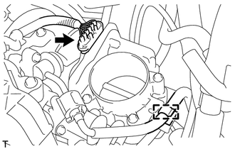
(c) Disconnect the ventilation hose from the cylinder head cover. |
|

|
(d) Unlock the hose band and separate the air cleaner cap sub-assembly from the throttle body assembly. |
|

|
(e) Remove the 2 bolts and air cleaner cap sub-assembly. |
|

10. REMOVE THROTTLE BODY ASSEMBLY
|
(a) Disconnect the throttle body assembly connector. |
|
(b) Disconnect the fuel tube from the clamp.
|
(c) Disconnect the 2 water by-pass hoses from the throttle body assembly. |
|

|
(d) Remove the 4 bolts and the throttle body assembly with the fuel tube bracket. |
|

|
(e) Remove the bolt and fuel tube bracket. |
|

|
(f) Remove the gasket from the intake manifold. |
|

 Inspection
INSPECTION
PROCEDURE
1. INSPECT THROTTLE BODY ASSEMBLY
Text in Illustration
*1
Component without harness connected
(Throttle Body)
(a) Check that the throttle v ...
 Installation
INSTALLATION
PROCEDURE
1. INSTALL THROTTLE BODY ASSEMBLY
(a) Install a new gasket to the intake manifold.
(b) Install the fuel ...
Other materials about Toyota Venza:
Problem Symptoms Table
PROBLEM SYMPTOMS TABLE
HINT:
Use the table below to help determine the cause of problem symptoms. If multiple
suspected areas are listed, the potential causes of the symptoms are listed in order
of probability in the "Suspected Area" column of ...
Driver Side Seat Belt Warning Light does not Operate
DESCRIPTION
When the ignition switch is ON, the center airbag sensor assembly transmits front
seat inner belt status signals to the combination meter assembly through CAN. If
the driver seat belt is not fastened, the combination meter assembly blinks the ...
Installation
INSTALLATION
PROCEDURE
1. INSTALL TELEVISION CAMERA ASSEMBLY (w/ Rear View Monitor System)
2. INSTALL BACK DOOR OPENER SWITCH ASSEMBLY
3. INSTALL NO. 1 BACK DOOR EMBLEM
4. INSTALL NO. 2 BACK DOOR NAME PLATE
5. INSTALL BACK DOOR OUTSIDE GARNIS ...

0.1243