Toyota Venza: Radio Antenna
Components
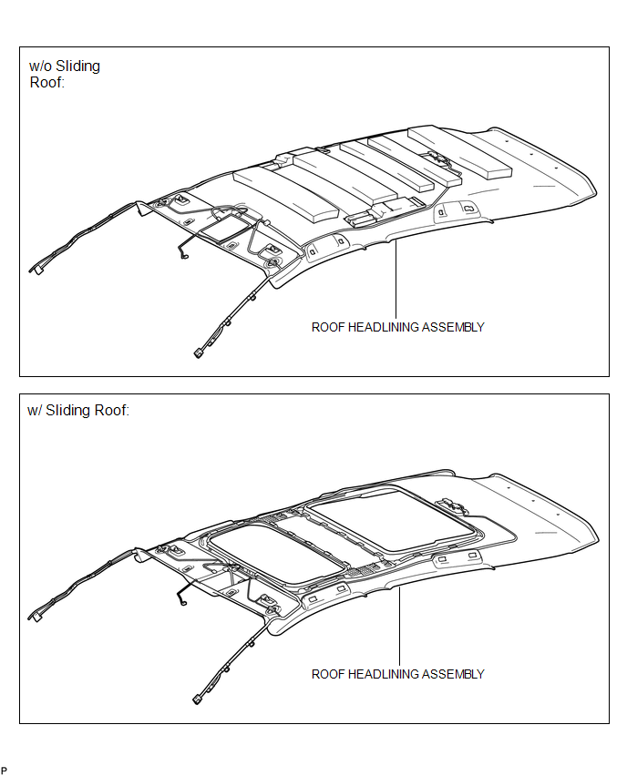
COMPONENTS
ILLUSTRATION
ILLUSTRATION

Installation
INSTALLATION
PROCEDURE
1. INSTALL RADIO ANTENNA ASSEMBLY
(a) Engage the 2 claws to install the radio antenna assembly.
|
(b) Place the antenna cord in the cutout of the antenna nut. Text in Illustration
|
|

(c) Install the radio antenna assembly with the antenna nut.
Torque:
4.5 N·m {46 kgf·cm, 40 in·lbf}
(d) Connect the 2 connectors.
2. INSTALL ROOF ANTENNA POLE SUB-ASSEMBLY
3. INSTALL ROOF HEADLINING ASSEMBLY
(See page .gif) )
)
Removal
REMOVAL
PROCEDURE
1. REMOVE ROOF HEADLINING ASSEMBLY
(See page .gif) )
)
2. REMOVE ROOF ANTENNA POLE SUB-ASSEMBLY
3. REMOVE RADIO ANTENNA ASSEMBLY
|
(a) Disconnect the 2 connectors. |
|

|
(b) Remove the antenna nut. |
|

|
(c) Disengage the 2 claws and remove the radio antenna assembly. |
|

 Microphone
Components
COMPONENTS
ILLUSTRATION
Removal
REMOVAL
PROCEDURE
1. REMOVE INNER REAR VIEW MIRROR STAY HOLDER COVER
2. REMOVE TELEPHONE MICROPHONE ASSEMBLY (INNER REAR VIEW MIRROR ASSEMBLY ...

Other materials about Toyota Venza:
All Doors LOCK/UNLOCK Functions do not Operate Via Door Control Switch
DESCRIPTION
The main body ECU (driver side junction block assembly) receives switch signals
from the door control switch and activates the door lock motor on each door according
to these signals.
WIRING DIAGRAM
PROCEDURE
1.
REA ...
Tire Pressure Warning Receiver
Components
COMPONENTS
ILLUSTRATION
Removal
REMOVAL
PROCEDURE
1. DISCONNECT CABLE FROM NEGATIVE BATTERY TERMINAL
NOTICE:
When disconnecting the cable, some systems need to be initialized after the cable
is reconnected (See page ).
2. REMOVE RO ...
Brake Line
Precaution
PRECAUTION
1. TROUBLESHOOTING PRECAUTION
NOTICE:
Since the brake lines are critical safety related parts, be sure to
disassemble and inspect the components if a brake fluid leak is found. If
any abnormality is found, replace th ...

0.158