Toyota Venza: Navigation Antenna
Components
COMPONENTS
ILLUSTRATION

Removal
REMOVAL
PROCEDURE
1. REMOVE INSTRUMENT PANEL SAFETY PAD ASSEMBLY
HINT:
Refer to the procedure up to Remove Instrument Panel Safety Pad Assembly (See
page .gif) ).
).
2. REMOVE NO. 1 SIDE DEFROSTER NOZZLE DUCT
3. REMOVE NO. 2 SIDE DEFROSTER NOZZLE DUCT
4. REMOVE DEFROSTER NOZZLE ASSEMBLY
5. REMOVE HEATER TO REGISTER DUCT
6. REMOVE NAVIGATION ANTENNA ASSEMBLY
|
(a) Disengage the 4 clamps. |
|
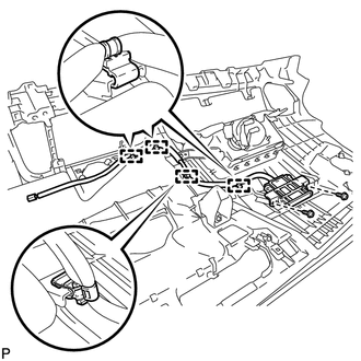
(b) Remove the 2 screws and the navigation antenna assembly.
Installation
INSTALLATION
PROCEDURE
1. INSTALL NAVIGATION ANTENNA ASSEMBLY
|
(a) Install the navigation antenna assembly with the 2 screws. |
|
.png)
(b) Engage the 4 clamps.
2. INSTALL HEATER TO REGISTER DUCT
.gif)
3. INSTALL DEFROSTER NOZZLE ASSEMBLY
4. INSTALL NO. 2 SIDE DEFROSTER NOZZLE DUCT
5. INSTALL NO. 1 SIDE DEFROSTER NOZZLE DUCT
6. INSTALL INSTRUMENT PANEL SAFETY PAD ASSEMBLY
HINT:
Refer to the procedure from Install Roof Headlining Assembly (See page
).


Other materials about Toyota Venza:
Components
COMPONENTS
ILLUSTRATION
ILLUSTRATION
ILLUSTRATION
ILLUSTRATION
ILLUSTRATION
ILLUSTRATION
...
How To Proceed With Troubleshooting
CAUTION / NOTICE / HINT
HINT:
The back door closer system troubleshooting procedure is based on the
premise that the power back door system is operating normally. Check the
power back door system first before troubleshooting the back door clo ...
Sound Quality is Bad Only when CD is Played (Volume is Too Low)
PROCEDURE
1.
REPLACE CD AND RECHECK
(a) Replace the CD with a new or known good one and check that the malfunction
disappears.
OK:
Malfunction disappears.
OK
END
NG
REPLACE ...

0.1389