Toyota Venza: Lost Communication with "Door Control Module B" (U0200)
DESCRIPTION
|
DTC No. |
DTC Detection Condition |
Trouble Area |
|---|---|---|
|
U0200 |
No communication from the outer mirror control ECU assembly (for driver side). |
|
WIRING DIAGRAM

CAUTION / NOTICE / HINT
NOTICE:
- Turn the ignition switch off before measuring the resistances between CAN bus main wires and between CAN bus branch wires.
- Turn the ignition switch off before inspecting CAN bus wires for a ground short.
- After the ignition switch is turned off, check that the key reminder warning system and light reminder warning system are not operating.
- Before measuring the resistance, leave the vehicle as is for at least 1 minute and do not operate the ignition switch, any other switches or the doors. If any doors need to be opened in order to check connectors, open the doors and leave them open.
HINT:
- Operating the ignition switch, any other switches or a door triggers related ECU and sensor communication on the CAN. This communication will cause the resistance value to change.
- Even after DTCs are cleared, if a DTC is stored again after driving the vehicle for a while, the malfunction may be occurring due to vibration of the vehicle. In such a case, wiggling the ECUs or wire harness while performing the inspection below may help determine the cause of the malfunction.
PROCEDURE
|
1. |
RECONFIRM DTC OUTPUT |
(a) Reconfirm DTCs.
HINT:
If CAN MS bus DTC U1002 is output from the main body ECU (Techstream display: Main Body), troubleshoot for U1002 and check for malfunctions in the CAN MS bus circuit.
|
Result |
Proceed to |
|---|---|
|
U1002 is not output from main body ECU (Techstream display: Main Body) |
A |
|
U1002 is output from main body ECU (Techstream display: Main Body) |
B |
| B | .gif) |
GO TO CIRCUITS INDICATED BY OUTPUT DTCS |
|
.gif)
|
2. |
CHECK FOR OPEN IN CAN BUS WIRES (OUTER MIRROR CONTROL ECU ASSEMBLY BRANCH WIRE) |
(a) Turn the ignition switch off.
|
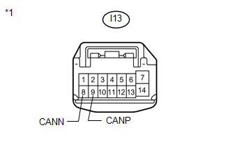
(b) Disconnect the outer mirror control ECU assembly (for driver side) connector. Text in Illustration
|
|
(c) Measure the resistance according to the value(s) in the table below.
Standard Resistance:
|
Tester Connection |
Condition |
Specified Condition |
|---|---|---|
|
I13-9 (CANP) - I13-8 (CANN) |
Ignition switch off |
54 to 69 Ω |
| NG | |
REPAIR OR REPLACE CAN BUS BRANCH WIRE OR CONNECTOR (OUTER MIRROR CONTROL ECU ASSEMBLY BRANCH WIRE) |
|
|
3. |
CHECK HARNESS AND CONNECTOR (POWER SOURCE TERMINAL) |
|
(a) Measure the voltage according to the value(s) in the table below. Standard Voltage:
|
|

| NG | |
REPAIR OR REPLACE HARNESS OR CONNECTOR (POWER SOURCE CIRCUIT) |
|
|
4. |
CHECK HARNESS AND CONNECTOR (GROUND TERMINAL) |
|
(a) Measure the resistance according to the value(s) in the table below. Standard Resistance:
|
|

| OK | |
REPLACE OUTER MIRROR CONTROL ECU ASSEMBLY (FOR DRIVER SIDE) |
| NG | |
REPAIR OR REPLACE HARNESS OR CONNECTOR (GROUND CIRCUIT) |
 Lost Communication with "Door Control Module A" (U0199)
DESCRIPTION
DTC No.
DTC Detection Condition
Trouble Area
U0199
No communication from the outer mirror control ECU (for front passenger
...
 Lost Communication with ECM / PCM (U0100)
DESCRIPTION
DTC No.
DTC Detection Condition
Trouble Area
U0100
No communication from the ECM continues.
ECM main wir ...
Other materials about Toyota Venza:
Adjusting the settings
- Adjusting the temperature setting
Turn the temperature control dial clockwise (warm) or counterclockwise (cool).
The air conditioning system switches between dual and simultaneous modes each
time is pressed.
Each temperature setting will be displ ...
TC and CG Terminal Circuit
DESCRIPTION
Connecting terminals TC and CG of the DLC3 causes the AWD control ECU to display
2-digit DTCs by flashing the AWD warning light.
HINT:
When each warning light remains blinking, a short to ground in the wiring of
terminal TC of the DLC3 or an ...
Relay
On-vehicle Inspection
ON-VEHICLE INSPECTION
PROCEDURE
1. INSPECT HORN RELAY (ENGINE ROOM JUNCTION BLOCK ASSEMBLY)
(a) Remove the engine room junction block assembly from the engine room
relay block (See page ).
...

0.1306