Toyota Venza: IG Power Source Circuit
DESCRIPTION
The main power source is supplied to the A/C amplifier when the ignition switch is ON.
The power source is used for operating the A/C amplifier and servo motor, etc.
WIRING DIAGRAM

CAUTION / NOTICE / HINT
NOTICE:
Inspect the fuses for circuits related to this system before performing the following inspection procedure.
HINT:
Start the engine before inspection. Check the IG1 relay or battery if the engine does not start.
PROCEDURE
|
1. |
INSPECT A/C AMPLIFIER |
|
(a) Remove the A/C amplifier with its connectors still connected. |
|

(b) Measure the voltage according to the value(s) in the table below.
Standard Voltage:
|
Tester Connection |
Condition |
Specified Condition |
|---|---|---|
|
D47-1 (IG+) - D47-14 (GND) |
Ignition switch off |
Below 1 V |
|
D47-1 (IG+) - D47-14 (GND) |
Ignition switch ON |
11 to 14 V |
|
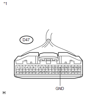
*1 |
Component with harness connected (A/C Amplifier) |
| OK | .gif) |
PROCEED TO NEXT SUSPECTED AREA SHOWN IN PROBLEM SYMPTOMS TABLE |
|
.gif)
|
2. |
CHECK HARNESS AND CONNECTOR (A/C AMPLIFIER - BATTERY) |
|
(a) Disconnect the A/C amplifier connector. |
|

(b) Measure the voltage according to the value(s) in the table below.
Standard Voltage:
|
Tester Connection |
Condition |
Specified Condition |
|---|---|---|
|
D47-1 (IG+) - Body ground |
Ignition switch off |
Below 1 V |
|
D47-1 (IG+) - Body ground |
Ignition switch ON |
11 to 14 V |
|
*1 |
Front view of wire harness connector (to A/C Amplifier) |
| NG | |
REPAIR OR REPLACE HARNESS OR CONNECTOR |
|
|
3. |
CHECK HARNESS AND CONNECTOR (A/C AMPLIFIER - BODY GROUND) |
|
(a) Measure the resistance according to the value(s) in the table below. Standard Resistance:
|
|
| OK | |
REPLACE A/C AMPLIFIER |
| NG | |
REPAIR OR REPLACE HARNESS OR CONNECTOR |
 Blower Motor Circuit
DESCRIPTION
The blower motor is operated by signals from the A/C amplifier. Blower motor
speed signals are transmitted in accordance with changes in the duty ratio.
WIRING DIAGRAM
CAUTION / NOT ...
 Back-up Power Source Circuit
DESCRIPTION
The back-up power source circuit for the A/C amplifier is shown below. Power
is supplied even when the ignition switch is turned off. The power is used for diagnostic
trouble code mem ...
Other materials about Toyota Venza:
Precaution
PRECAUTION
NOTICE:
When disconnecting the cable from the negative (-) battery terminal, initialize
the following systems after the cable is reconnected.
System Name
See Procedure
Back Door Closer System
...
Removal
REMOVAL
CAUTION / NOTICE / HINT
HINT:
Use the same procedure for the RH side and LH side.
The procedure listed below is for the LH side.
PROCEDURE
1. PRECAUTION
CAUTION:
Be sure to read Precaution thoroughly before servicing (See page
...
Pressure Sensor Circuit (B1423/23)
DESCRIPTION
This DTC is output when refrigerant pressure on the high pressure side is extremely
low (190 kPa (1.9 kgf/cm2, 28 psi) or less) or extremely high (3140 kPa (32.0 kgf/cm2,
455 psi) or more). The A/C pressure sensor is installed on the high pres ...

0.1172