Toyota Venza: Washer Motor(for Rear Side)
Components
COMPONENTS
ILLUSTRATION

Removal
REMOVAL
PROCEDURE
1. REMOVE FRONT WHEEL RH
2. REMOVE FRONT FENDER OUTSIDE MOULDING RH
HINT:
Use the same procedure for the RH side and LH side (See page
.gif) ).
).
3. REMOVE FRONT FENDER LINER RH
4. DRAIN WINDSHIELD WASHER FLUID
|
(a) Disconnect the washer hose from the rear washer motor and pump assembly, and drain the washer fluid. HINT: Use a container to collect the washer fluid. |
|

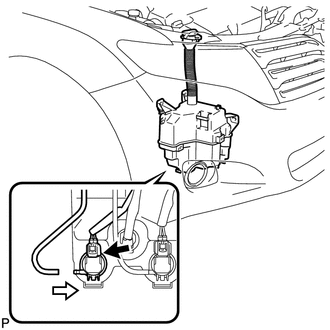
5. REMOVE REAR WASHER MOTOR AND PUMP ASSEMBLY
|
(a) Disconnect the connector. |
|

(b) Remove the rear washer motor and pump assembly.
HINT:
Use a container to collect the washer fluid.
Inspection
INSPECTION
PROCEDURE
1. INSPECT REAR WASHER MOTOR AND PUMP ASSEMBLY
(a) Remove the washer jar.
(b) Disconnect the rear washer motor and pump connector.
HINT:
The check should be performed with the rear washer motor and pump installed on the washer jar.
(c) Fill the washer jar with washer fluid.
|
(d) Connect a battery positive (+) lead to terminal 1 of the rear washer motor and pump, and a negative (-) lead to terminal 2. |
|

(e) Check that washer fluid flows from the washer jar.
OK:
Washer fluid flows from the washer jar.
If the result is not as specified, replace the rear washer motor and pump assembly.
Text in Illustration|
*1 |
Component without harness connected (Rear Washer Motor and Pump Assembly) |
Installation
INSTALLATION
PROCEDURE
1. INSTALL REAR WASHER MOTOR AND PUMP ASSEMBLY
|
(a) Install the rear washer motor and pump assembly. |
|
(b) Connect the connector.
(c) Connect the washer hose.
2. FILL WASHER JAR WITH WASHER FLUID
(a) Fill the washer jar with washer fluid.
3. INSTALL FRONT FENDER LINER RH
.gif)
4. INSTALL FRONT FENDER OUTSIDE MOULDING RH
HINT:
Use the same procedure for the RH side and LH side (See page
).
5. INSTALL FRONT WHEEL RH
 Washer Motor(for Front Side)
Components
COMPONENTS
ILLUSTRATION
Removal
REMOVAL
PROCEDURE
1. REMOVE FRONT WHEEL RH
2. REMOVE FRONT FENDER OUTSIDE MOULDING RH
HINT:
Use the same procedure for the RH side and LH side ...
 Washer Nozzle(for Front Side)
Components
COMPONENTS
ILLUSTRATION
On-vehicle Inspection
ON-VEHICLE INSPECTION
PROCEDURE
1. INSPECT FRONT WASHER NOZZLE SUB-ASSEMBLY
(a) With the engine running, check that the center str ...
Other materials about Toyota Venza:
Wheels
If a wheel is bent, cracked or heavily corroded, it should be replaced.
Otherwise, the tire may separate from the wheel or cause loss of handling control.
- Wheel selection
When replacing wheels, care should be taken to ensure that they are equivalent ...
Relay
On-vehicle Inspection
ON-VEHICLE INSPECTION
PROCEDURE
1. FAN NO. 1 RELAY
(a) Remove the relay from the engine room relay block.
(b) Measure the resistance according to the value(s) in the table b ...
XM Tuner Malfunction (B15BA)
DESCRIPTION
These DTCs are stored when a malfunction occurs in the stereo component tuner
assembly.
DTC No.
DTC Detection Condition
Trouble Area
B15BA
When either of the following conditions is m ...

0.1231