Toyota Venza: Solar Sensor
Components
COMPONENTS
ILLUSTRATION

On-vehicle Inspection
ON-VEHICLE INSPECTION
PROCEDURE
1. INSPECT SOLAR SENSOR
|
(a) Disconnect the solar sensor connector. |
|

(b) Measure the voltage according to the value(s) in the table below.
Standard Voltage:
|
Tester Connection |
Condition |
Specified Condition |
|---|---|---|
|
6 (CLTB) - 3 (CLTE) |
Engine switch off |
Below 1 V |
|
6 (CLTB) - 3 (CLTE) |
Engine switch on (IG) |
11 to 14 V |
If the voltage is not as specified, repair or replace the wire harness or connector.
|
(c) Reconnect the solar sensor connector. |
|
(d) Turn the engine switch on (IG).
(e) Measure the voltage according to the value(s) in the table below.
Standard Voltage:
|
Tester Connection |
Condition |
Specified Condition |
|---|---|---|
|
1 (TSL) - 3 (CLTE) |
Sensor is subjected to electric light |
0.8 to 4.3 V |
|
1 (TSL) - 3 (CLTE) |
Sensor is covered by a cloth |
Below 0.8 V |
|
2 (TSR) - 3 (CLTE) |
Sensor is subjected to electric light |
0.8 to 4.3 V |
|
2 (TSR) - 3 (CLTE) |
Sensor is covered by a cloth |
Below 0.8 V |
NOTICE:
- The connection procedure for using a digital tester such as a TOYOTA electrical tester is shown above. When using an analog tester, connect the positive (+) lead to terminal 6 and the negative (-) lead to terminal 2 (1) of the solar sensor.
- While using the battery during inspection, do not bring the positive and negative tester probes too close to each other as a short circuit may occur.
HINT:
- Use an incandescent light for inspection. Bring it within about 30 cm (11.8 in.) of the solar sensor.
- As the inspection light is moved away from the sensor, the voltage decreases.
If the voltage is not as specified, replace the solar sensor.
Text in Illustration|
*1 |
Front view of wire harness connector (to Solar Sensor) |
|
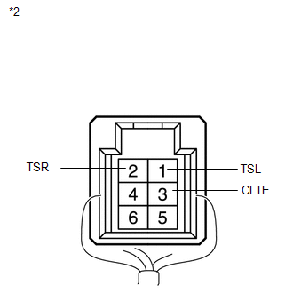
*2 |
Component with harness connected (Solar Sensor) |
Removal
REMOVAL
PROCEDURE
1. DISCONNECT CABLE FROM NEGATIVE BATTERY TERMINAL
NOTICE:
When disconnecting the cable, some systems need to be initialized after the cable
is reconnected (See page .gif) ).
).
2. REMOVE DEFROSTER NOZZLE GARNISH
3. REMOVE SOLAR SENSOR
|
(a) Disengage the 2 claws and remove the solar sensor. |
|

Installation
INSTALLATION
PROCEDURE
1. INSTALL SOLAR SENSOR
|
(a) Engage the 2 claws to install the solar sensor. |
|
.png)
2. INSTALL DEFROSTER NOZZLE GARNISH
.gif)
3. CONNECT CABLE TO NEGATIVE BATTERY TERMINAL
NOTICE:
When disconnecting the cable, some systems need to be initialized after the cable
is reconnected (See page ).
 Room Temperature Sensor
Components
COMPONENTS
ILLUSTRATION
Removal
REMOVAL
PROCEDURE
1. DISCONNECT CABLE FROM NEGATIVE BATTERY TERMINAL
NOTICE:
When disconnecting the cable, some systems need to be initialized ...

Other materials about Toyota Venza:
Brake Pedal Load Sensing Switch (C1267/67)
DESCRIPTION
The brake pedal load sensing switch is turned on when the brake pedal is depressed
with force exceeding a predetermined level.
The skid control ECU detects if the brake pedal is depressed or not via this
circuit.
DTC Code
...
Disassembly
DISASSEMBLY
CAUTION / NOTICE / HINT
NOTICE:
When disassembling the multiplex network door ECU, eliminate static electricity
by touching the vehicle body to prevent the components from being damaged.
PROCEDURE
1. REMOVE MULTIPLEX NETWORK DOOR ECU
...
Fuel pump shut off system
To minimize the risk of fuel leakage when the engine stalls or an airbag inflates
upon collision, the fuel pump shut off system stops supplying fuel to the engine.
Follow the procedure below to restart the engine after the system is activated.
►Vehic ...

0.1556