Toyota Venza: Short to GND in Immobiliser System Power Source Circuit (B278A)
DESCRIPTION
This DTC is stored when the engine switch power source supply line is open or shorted.
|
DTC No. |
DTC Detection Condition |
Trouble Area |
|---|---|---|
|
B278A |
Engine switch power source supply line is open or shorted. |
|
WIRING DIAGRAM

CAUTION / NOTICE / HINT
NOTICE:
If the certification ECU (smart key ECU assembly) is replaced, register the key
(See page .gif) ).
).
PROCEDURE
|
1. |
CHECK DTC OUTPUT |
(a) Clear the DTCs (See page ).
(b) Recheck for DTCs (See page ).
OK:
DTC B278A is not output.
| OK | .gif) |
USE SIMULATION METHOD TO CHECK |
|
.gif)
|
2. |
CHECK HARNESS AND CONNECTOR (CERTIFICATION ECU - ENGINE SWITCH) |
(a) Disconnect the certification ECU (smart key ECU assembly) connector.
|
(b) Disconnect the engine switch connector. |
|
(c) Measure the resistance according to the value(s) in the table below.
Standard Resistance:
|
Tester Connection |
Condition |
Specified Condition |
|---|---|---|
|
D25-28 (VC5) - D13-14 (VC5) |
Always |
Below 1 Ω |
|
D25-36 (AGND) - D13-8 (AGND) |
Always |
Below 1 Ω |
|
D25-28 (VC5) - Body ground |
Always |
10 kΩ or higher |
|
D25-36 (AGND) - Body ground |
Always |
10 kΩ or higher |
|
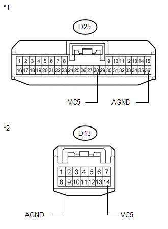
*1 |
Front view of wire harness connector (to Certification ECU (Smart Key ECU Assembly)) |
|
*2 |
Front view of wire harness connector (to Engine Switch) |
| NG | |
REPAIR OR REPLACE HARNESS OR CONNECTOR |
|
|
3. |
CHECK CERTIFICATION ECU (SMART KEY ECU ASSEMBLY) |
(a) Reconnect the certification ECU (smart key ECU assembly) connector.
(b) Reconnect the engine switch connector.
(c) Using an oscilloscope, check the waveform.

Waveform (Reference):
|
Item |
Content |
|---|---|
|
Tester Connection |
D25-28 (VC5) - D25-36 (AGND) |
|
Tool Setting |
2 V/DIV., 200 ms./DIV. |
|
Condition |
|
OK:
Waveform is output normally (see illustration)
|
Result |
Proceed to |
|---|---|
|
NG |
A |
|
OK (for 2GR-FE) |
B |
|
OK (for 1AR-FE) |
C |
|
*1 |
Component with harness connected (Certification ECU (Smart Key ECU Assembly)) |
|
*2 |
GND |
| A | |
REPLACE CERTIFICATION ECU (SMART KEY ECU ASSEMBLY) |
| B | |
REPLACE ENGINE SWITCH |
| C | |
REPLACE ENGINE SWITCH |
 Theft Deterrent System Communication Line High Fixation (B279A)
DESCRIPTION
If the communication line (EFIO - IMI) to the certification ECU (smart key ECU
assembly) is stuck high output (e.g. shorted to +B), the ECM stores this DTC.
DTC No.
...
 Engine Immobiliser System Malfunction (B2799)
DESCRIPTION
This DTC is stored when one of the following occurs: 1) the ECM detects an error
in its own communication with the certification ECU (smart key ECU assembly); 2)
the ECM detects an er ...
Other materials about Toyota Venza:
No Communication in Immobiliser System (B2796,B2798)
DESCRIPTION
These DTCs are stored if a key that does not have a transponder chip is inserted
into the ignition key cylinder or if communication between the key and the transponder
key ECU assembly is impossible.
DTC No.
DTC Detectio ...
Engine Hood Courtesy Switch Circuit
DESCRIPTION
The security courtesy switch is installed together with the hood lock. This switch
turns off when the engine hood is opened and turns on when the engine hood is closed.
WIRING DIAGRAM
PROCEDURE
1.
INSPECT HOOD LOCK AS ...
Terminals Of Ecu
TERMINALS OF ECU
1. TCM
HINT:
Each TCM terminal standard voltage is shown in the table below.
In the table, first follow the information under "Condition". Look under "Terminal
No. (Symbol)" for the terminals to be inspected. The st ...

0.1489