Toyota Venza: Removal
REMOVAL
CAUTION / NOTICE / HINT
HINT:
- Use the same procedure for the RH side and LH side.
- The procedure listed below is for the LH side.
PROCEDURE
1. REMOVE FRONT WHEEL
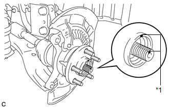
2. REMOVE FRONT AXLE SHAFT NUT
.gif)
3. SEPARATE FRONT SPEED SENSOR
|
(a) Remove the bolt and resin clamp, and separate the front speed sensor. Text in Illustration
NOTICE:
|
|

4. SEPARATE FRONT DISC BRAKE CALIPER ASSEMBLY
5. REMOVE FRONT DISC
6. SEPARATE TIE ROD ASSEMBLY
7. SEPARATE FRONT LOWER SUSPENSION ARM
|
(a) Remove the bolt and 2 nuts, and separate the front lower suspension arm from the front lower ball joint. |
|

8. SEPARATE FRONT DRIVE SHAFT ASSEMBLY
|
(a) Put matchmarks on the front drive shaft assembly and front axle hub sub-assembly. Text in Illustration
|
|
|
(b) Using a plastic hammer, separate the front drive shaft assembly from the front axle assembly. If it is difficult to separate, tap the end of the front drive shaft assembly using a brass bar and a hammer. NOTICE: Be careful not to damage the drive shaft boot and speed sensor rotor. |
|

9. REMOVE FRONT AXLE ASSEMBLY
|
(a) Remove the 2 bolts, 2 nuts and front axle assembly. NOTICE:
|
|

10. REMOVE FRONT NO. 1 WHEEL BEARING DUST DEFLECTOR
|
(a) Using a screwdriver with its tip wrapped with vinyl tape, remove the front No. 1 wheel bearing dust deflector. Text in Illustration
NOTICE: Be careful not to damage the steering knuckle. |
|

11. REMOVE FRONT AXLE HUB HOLE SNAP RING
|
(a) Using snap ring pliers, remove the front axle hub hole snap ring. |
|

12. REMOVE FRONT AXLE HUB SUB-ASSEMBLY
|
(a) Hold the front axle assembly between aluminum plates in a vise. NOTICE: Do not overtighten the vise. |
|

(b) Using SST, remove the front axle hub sub-assembly.
SST: 09520-00031
|
(c) Using SST and a press, remove the bearing inner race (outside) from the front axle hub sub-assembly. SST: 09555-55010 SST: 09950-60010 09951-00430 SST: 09950-70010 09951-07100 NOTICE: Be careful not to drop the front axle hub sub-assembly. |
|

13. REMOVE FRONT DISC BRAKE DUST COVER
|
(a) Remove the 4 bolts and front disc brake dust cover from the steering knuckle. |
|

14. REMOVE FRONT AXLE HUB BEARING
|
(a) Place the bearing inner race (outside) on the front axle hub bearing. |
|

(b) Using SST, V-blocks and a press, remove the front axle hub bearing from the steering knuckle.
If the steering knuckle cannot be kept level using SST, stabilize the steering knuckle using a washer or an equivalent tool.
Text in Illustration|
*1 |
V-block |
SST: 09527-21011
SST: 09950-60010
09951-00440
09952-06010
SST: 09950-60020
09951-00750
SST: 09950-70010
09951-07100
NOTICE:
Keep the steering knuckle level.
 On-vehicle Inspection
ON-VEHICLE INSPECTION
CAUTION / NOTICE / HINT
HINT:
Use the same procedure for the RH side and LH side.
The procedure listed below is for the LH side.
PROCEDURE
1. REMOVE FRONT ...
 Installation
INSTALLATION
CAUTION / NOTICE / HINT
HINT:
Use the same procedure for the RH side and LH side.
The procedure listed below is for the LH side.
PROCEDURE
1. INSTALL FRONT AXLE HUB ...
Other materials about Toyota Venza:
Front Passenger Side Power Window Switch
Components
COMPONENTS
ILLUSTRATION
Removal
REMOVAL
PROCEDURE
1. REMOVE POWER WINDOW REGULATOR SWITCH ASSEMBLY WITH FRONT DOOR ARMREST BASE
PANEL
(a) Using a moulding remover, disengage the 2 clips and 4 claws.
...
How To Proceed With Troubleshooting
CAUTION / NOTICE / HINT
HINT:
Use the following procedure to troubleshoot.
*: Use the Techstream.
PROCEDURE
1.
VEHICLE BROUGHT TO WORKSHOP
NEXT
...
Reassembly
REASSEMBLY
PROCEDURE
1. INSTALL GENERATOR ROTOR ASSEMBLY
(a) Place the drive end frame on the clutch pulley.
(b) Install the generator rotor assembly to the drive end frame.
2. INSTALL GENERATOR CL ...

0.1558