Toyota Venza: Removal
REMOVAL
PROCEDURE
1. REMOVE WINDSHIELD WIPER MOTOR AND LINK
(a) Remove the windshield wiper motor and link (See page
.gif) ).
).
2. REMOVE OUTER COWL TOP PANEL SUB-ASSEMBLY
3. REMOVE NO. 1 ENGINE COVER SUB-ASSEMBLY
4. REMOVE COOL AIR INTAKE DUCT SEAL
5. REMOVE NO. 1 ENGINE UNDER COVER
6. REMOVE NO. 2 ENGINE UNDER COVER
7. DRAIN ENGINE COOLANT
8. REMOVE NO. 1 VACUUM SWITCHING VALVE ASSEMBLY
9. REMOVE AIR CLEANER CAP SUB-ASSEMBLY
|
(a) Disconnect the mass air flow meter connector and separate the wire harness clamp from the air cleaner cap. |
|

(b) Separate the hose from the hose clamp.
|
(c) Disconnect the ventilation hose from the cylinder head cover. |
|

|
(d) Unlock the hose band and separate the air cleaner cap sub-assembly from the throttle body assembly. |
|

|
(e) Remove the 2 bolts and air cleaner cap sub-assembly. |
|

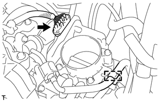
10. REMOVE THROTTLE BODY ASSEMBLY
|
(a) Disconnect the throttle body assembly connector. |
|
(b) Disconnect the fuel tube from the clamp.
|
(c) Disconnect the 2 water by-pass hoses from the throttle body assembly. |
|

|
(d) Remove the 4 bolts and the throttle body assembly with the fuel tube bracket. |
|

|
(e) Remove the bolt and fuel tube bracket. |
|

|
(f) Remove the gasket from the intake manifold. |
|

 Inspection
INSPECTION
PROCEDURE
1. INSPECT THROTTLE BODY ASSEMBLY
Text in Illustration
*1
Component without harness connected
(Throttle Body)
(a) Check that the throttle v ...
 Installation
INSTALLATION
PROCEDURE
1. INSTALL THROTTLE BODY ASSEMBLY
(a) Install a new gasket to the intake manifold.
(b) Install the fuel ...
Other materials about Toyota Venza:
Installation
INSTALLATION
PROCEDURE
1. INSTALL REAR CENTER SEAT OUTER BELT ASSEMBLY
(a) Install the rear center seat outer belt assembly with the bolt and
nut.
Torque:
Bolt :
7.5 N·m {77 kgf·cm, 66 in·lbf}
Nut :
42 N·m {428 kgf·cm, ...
System Description
SYSTEM DESCRIPTION
1. TOUCH SWITCH OUTLINE
(a) Touch switches are touch-sensitive (interactive) switches operated by touching
the screen. When a switch is pressed, the outer film bends in to contact the inner
glass at the pressed position. By doing this, ...
Windshield Deicer does not Operate
DESCRIPTION
When the rear window defogger switch on the air conditioning control assembly
is pressed, the operation signal is transmitted to the air conditioning amplifier
assembly through the LIN communication line. When the air conditioning amplifier
...

0.1272