Toyota Venza: Radio Antenna
Components
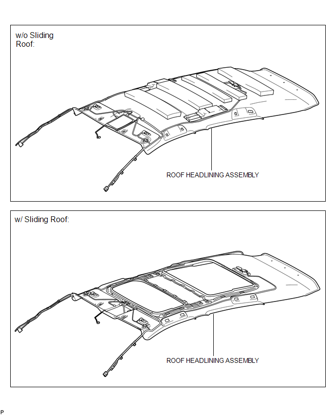
COMPONENTS
ILLUSTRATION
ILLUSTRATION

Installation
INSTALLATION
PROCEDURE
1. INSTALL RADIO ANTENNA ASSEMBLY
(a) Engage the 2 claws to install the radio antenna assembly.
|
(b) Place the antenna cord in the cutout of the antenna nut. Text in Illustration
|
|

(c) Install the radio antenna assembly with the antenna nut.
Torque:
4.5 N·m {46 kgf·cm, 40 in·lbf}
(d) Connect the 2 connectors.
2. INSTALL ROOF ANTENNA POLE SUB-ASSEMBLY
3. INSTALL ROOF HEADLINING ASSEMBLY
(See page .gif) )
)
Removal
REMOVAL
PROCEDURE
1. REMOVE ROOF HEADLINING ASSEMBLY
(See page .gif) )
)
2. REMOVE ROOF ANTENNA POLE SUB-ASSEMBLY
3. REMOVE RADIO ANTENNA ASSEMBLY
|
(a) Disconnect the 2 connectors. |
|

|
(b) Remove the antenna nut. |
|

|
(c) Disengage the 2 claws and remove the radio antenna assembly. |
|

 Microphone
Components
COMPONENTS
ILLUSTRATION
Removal
REMOVAL
PROCEDURE
1. REMOVE INNER REAR VIEW MIRROR STAY HOLDER COVER
2. REMOVE TELEPHONE MICROPHONE ASSEMBLY (INNER REAR VIEW MIRROR ASSEMBLY ...

Other materials about Toyota Venza:
System Description
SYSTEM DESCRIPTION
1. ACCESSORY METER ASSEMBLY
(a) Warning or Indicator
Item
Detail
Front passenger side seat belt warning light
Receives a front passenger side seat belt warning light signal from the
co ...
Components
COMPONENTS
ILLUSTRATION
ILLUSTRATION
ILLUSTRATION
ILLUSTRATION
ILLUSTRATION
ILLUSTRATION
...
Security Horn Circuit
DESCRIPTION
When the theft deterrent system is switched from the armed state to the alarm
sounding state, the main body ECU (driver side junction block assembly) controls
the security horn.
WIRING DIAGRAM
PROCEDURE
1.
PERFORM A ...

0.1164