Toyota Venza: Navigation Antenna
Components
COMPONENTS
ILLUSTRATION

Removal
REMOVAL
PROCEDURE
1. REMOVE INSTRUMENT PANEL SAFETY PAD ASSEMBLY
HINT:
Refer to the procedure up to Remove Instrument Panel Safety Pad Assembly (See
page .gif) ).
).
2. REMOVE NO. 1 SIDE DEFROSTER NOZZLE DUCT
3. REMOVE NO. 2 SIDE DEFROSTER NOZZLE DUCT
4. REMOVE DEFROSTER NOZZLE ASSEMBLY
5. REMOVE HEATER TO REGISTER DUCT
6. REMOVE NAVIGATION ANTENNA ASSEMBLY
|
(a) Disengage the 4 clamps. |
|
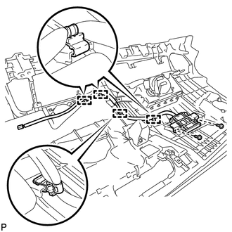
(b) Remove the 2 screws and the navigation antenna assembly.
Installation
INSTALLATION
PROCEDURE
1. INSTALL NAVIGATION ANTENNA ASSEMBLY
|
(a) Install the navigation antenna assembly with the 2 screws. |
|
.png)
(b) Engage the 4 clamps.
2. INSTALL HEATER TO REGISTER DUCT
.gif)
3. INSTALL DEFROSTER NOZZLE ASSEMBLY
4. INSTALL NO. 2 SIDE DEFROSTER NOZZLE DUCT
5. INSTALL NO. 1 SIDE DEFROSTER NOZZLE DUCT
6. INSTALL INSTRUMENT PANEL SAFETY PAD ASSEMBLY
HINT:
Refer to the procedure from Install Roof Headlining Assembly (See page
).


Other materials about Toyota Venza:
Diagnostic Trouble Code Chart
DIAGNOSTIC TROUBLE CODE CHART
If a trouble code is displayed during the DTC check, check the circuit listed
for the code in the table below (proceed to the page listed for that circuit).
HINT:
When DTC B1650/32 is detected as a result of troubleshooting f ...
Road Test
ROAD TEST
1. PROBLEM SYMPTOM CONFIRMATION
(a) Inspect the SET function.
Text in Illustration
*1
ON/OFF
*2
- SET
(1) Turn the cruise control main switch on.
(2) Drive at the required speed of bet ...
Replacement
REPLACEMENT
PROCEDURE
1. REPLACE RING PIN
NOTICE:
It is not necessary to remove the ring pin unless it is being replaced.
(a) Remove the 12 ring pins.
(b) Using a plastic-faced hammer, install 12 new ring pins.
Standard Protrusion Height:
...

0.168