Toyota Venza: Installation
INSTALLATION
PROCEDURE
1. INSTALL POWER OUTLET SOCKET COVER NO.1
|
(a) Engage the 2 claws to install the power point socket cover. |
|
.png)
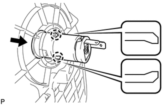
2. INSTALL POWER POINT SOCKET ASSEMBLY
|
(a) Engage the 2 claws to install the power point socket assembly as shown in the illustration. |
|
3. INSTALL CONSOLE BOX SUB-ASSEMBLY
.gif)
4. INSTALL POSITION INDICATOR HOUSING ASSEMBLY
5. INSTALL SHIFT LEVER KNOB SUB-ASSEMBLY
6. INSTALL LOWER INSTRUMENT PANEL SUB-ASSEMBLY
7. INSTALL NO. 2 INSTRUMENT PANEL UNDER COVER SUB-ASSEMBLY
8. INSTALL COWL SIDE TRIM SUB-ASSEMBLY RH
9. INSTALL FRONT DOOR SCUFF PLATE RH
10. INSTALL LOWER NO. 1 INSTRUMENT PANEL FINISH PANEL
11. INSTALL COWL SIDE TRIM SUB-ASSEMBLY LH
12. INSTALL FRONT DOOR SCUFF PLATE LH
13. INSTALL AIR CONDITIONING CONTROL ASSEMBLY
14. INSTALL CONSOLE BOX ASSEMBLY
15. INSTALL NO. 2 CONSOLE BOX CARPET
16. INSTALL UPPER CONSOLE PANEL SUB-ASSEMBLY (w/o Seat Heater System)
17. INSTALL UPPER CONSOLE PANEL SUB-ASSEMBLY (w/ Seat Heater System)
 Removal
REMOVAL
PROCEDURE
1. REMOVE UPPER CONSOLE PANEL SUB-ASSEMBLY (w/o Seat Heater System)
2. REMOVE UPPER CONSOLE PANEL SUB-ASSEMBLY (w/ Seat Heater System)
3. REMOVE NO. 2 CONSOLE BOX CARPET
...

Other materials about Toyota Venza:
Open in Front Passenger Side Electrical Antenna Circuit (B27A2)
DESCRIPTION
The certification ECU (smart key ECU assembly) generates a request signal and
sends it to the door electrical key oscillator built into the front door outside
handle assembly (for front passenger side) at 0.25-second intervals. To detect a
k ...
Precaution
PRECAUTION
NOTICE:
When disconnecting the cable from the negative (-) battery terminal, initialize
the following systems after the cable is reconnected.
System Name
See Procedure
Power back door system
...
Detecting Vehicle Submersion (B2277)
DESCRIPTION
This DTC is stored when the submersion circuit monitor inside the power management
control ECU detects a large amount of water.
DTC No.
DTC Detection Condition
Trouble Area
B2277
The ...

0.1358