Toyota Venza: Inspection
INSPECTION
PROCEDURE
1. INSPECT PRELOAD
|
(a) Using SST and a torque wrench, measure the preload of the backlash between the driven pinion and ring gear. SST: 09326-20011 Preload (at Starting):
HINT:
|
|

(b) Using SST and a torque wrench, measure the total preload.
SST: 09326-20011
Preload (at Starting):
|
Item |
Preload |
|---|---|
|
without SST |
0.35 to 0.53 N*m (4 to 5 kgf*cm, 3 to 4 in.*lbf) + driven pinion preload |
|
with SST |
0.25 to 0.38 N*m (3 to 4 kgf*cm, 3 to 3.3 in.*lbf) + driven pinion preload |
HINT:
- Use a torque wrench with a fulcrum length of 130 mm (5.12 in.).
- Turn the driven pinion counterclockwise and clockwise several times.

If the preload is outside the specified range, replace the No. 2 transfer ring gear mounting case washer with one that is thicker or thinner as necessary and recheck.
Text in Illustration|
*1 |
No. 2 Transfer Ring Gear Mounting Case Washer |
|
Mark |
Thickness |
Mark |
Thickness |
|---|---|---|---|
|
G7 |
2.47 (0.0972) |
M7 |
3.47 (0.1366) |
|
G8 |
2.49 (0.0980) |
M8 |
3.49 (0.1374) |
|
G9 |
2.51 (0.0988) |
M9 |
3.51 (0.1382) |
|
H0 |
2.53 (0.0996) |
N0 |
3.53 (0.1390) |
|
H1 |
2.55 (0.1004) |
N1 |
3.55 (0.1398) |
|
H2 |
2.57 (0.1012) |
N2 |
3.57 (0.1406) |
|
H3 |
2.59 (0.1020) |
N3 |
3.59 (0.1413) |
|
H4 |
2.61 (0.1028) |
N4 |
3.61 (0.1421) |
|
H5 |
2.63 (0.1035) |
N5 |
3.63 (0.1429) |
|
H6 |
2.65 (0.1043) |
N6 |
3.65 (0.1437) |
|
H7 |
2.67 (0.1051) |
N7 |
3.67 (0.1445) |
|
H8 |
2.69 (0.1059) |
N8 |
3.69 (0.1453) |
|
H9 |
2.71 (0.1067) |
N9 |
3.71 (0.1461) |
|
J0 |
2.73 (0.1075) |
P0 |
3.73 (0.1469) |
|
J1 |
2.75 (0.1083) |
P1 |
3.75 (0.1476) |
|
J2 |
2.77 (0.1091) |
P2 |
3.77 (0.1484) |
|
J3 |
2.79 (0.1098) |
P3 |
3.79 (0.1492) |
|
J4 |
2.81 (0.1106) |
P4 |
3.81 (0.1500) |
|
J5 |
2.83 (0.1114) |
P5 |
3.83 (0.1508) |
|
J6 |
2.85 (0.1122) |
P6 |
3.85 (0.1516) |
|
J7 |
2.87 (0.1130) |
P7 |
3.87 (0.1524) |
|
J8 |
2.89 (0.1138) |
P8 |
3.89 (0.1531) |
|
J9 |
2.91 (0.1146) |
P9 |
3.91 (0.1539) |
|
K0 |
2.93 (0.1154) |
Q0 |
3.93 (0.1547) |
|
K1 |
2.95 (0.1161) |
Q1 |
3.95 (0.1555) |
|
K2 |
2.97 (0.1169) |
Q2 |
3.97 (0.1563) |
|
K3 |
2.99 (0.1177) |
Q3 |
3.99 (0.1571) |
|
K4 |
3.01 (0.1185) |
Q4 |
4.01 (0.1579) |
|
K5 |
3.03 (0.1193) |
Q5 |
4.03 (0.1587) |
|
K6 |
3.05 (0.1201) |
Q6 |
4.05 (0.1594) |
|
K7 |
3.07 (0.1209) |
Q7 |
4.07 (0.1602) |
|
K8 |
3.09 (0.1217) |
Q8 |
4.09 (0.1610) |
|
K9 |
3.11 (0.1224) |
Q9 |
4.11 (0.1618) |
|
L0 |
3.13 (0.1232) |
R0 |
4.13 (0.1626) |
|
L1 |
3.15 (0.1240) |
R1 |
4.15 (0.1634) |
|
L2 |
3.17 (0.1248) |
R2 |
4.17 (0.1642) |
|
L3 |
3.19 (0.1256) |
R3 |
4.19 (0.1650) |
|
L4 |
3.21 (0.1264) |
R4 |
4.21 (0.1657) |
|
L5 |
3.23 (0.1272) |
R5 |
4.23 (0.1665) |
|
L6 |
3.25 (0.1280) |
R6 |
4.25 (0.1673) |
|
L7 |
3.27 (0.1287) |
R7 |
4.27 (0.1681) |
|
L8 |
3.29 (0.1295) |
R8 |
4.29 (0.1689) |
|
L9 |
3.31 (0.1303) |
R9 |
4.31 (0.1697) |
|
M0 |
3.33 (0.1311) |
S0 |
4.33 (0.1705) |
|
M1 |
3.35 (0.1319) |
S1 |
4.35 (0.1713) |
|
M2 |
3.37 (0.1327) |
S2 |
4.37 (0.1720) |
|
M3 |
3.39 (0.1335) |
S3 |
4.39 (0.1728) |
|
M4 |
3.41 (0.1343) |
S4 |
4.41 (0.1736) |
|
M5 |
3.43 (0.1350) |
S5 |
4.43 (0.1744) |
|
M6 |
3.45 (0.1358) |
S6 |
4.45 (0.1752) |
2. INSPECT RING GEAR BACKLASH
|
(a) Using a dial indicator, check the backlash of the ring gear. Backlash: 0.14 to 0.25 mm (0.00551 to 0.00984 in.) If the backlash is not within the specification, adjust the side bearing preload or repair as necessary. NOTICE: Check at least 3 positions on the circumference of the ring gear. |
|

3. INSPECT TOOTH CONTACT BETWEEN RING GEAR AND DRIVE PINION
|
(a) Coat 3 or 4 teeth at 4 different positions on the ring gear with Prussian blue. |
|

(b) Turn the driven pinion to rotate the ring gear 10 times or more clockwise and 10 times or more counterclockwise.
(c) Rotate the ring gear to inspect the tooth pattern.
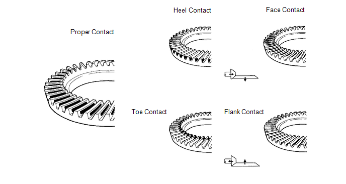
(d) If the tooth contact pattern is not correct, select a new transfer output shaft washer that is thicker or thinner as necessary and recheck.
4. INSPECT RUNOUT OF RING GEAR
|
(a) Place the transfer ring gear mounting case on the V-blocks. |
|

(b) Using a dial indicator, check the runout of the ring gear.
Maximum runout:
0.06 mm (0.00236 in.)
HINT:
If the runout is more than maximum, replace the ring gear with a new one.
5. INSPECT TRANSFER RING GEAR MOUNTING CASE
|
(a) Place the transfer ring gear mounting case on the V-blocks. |
|

(b) Using a dial indicator, check the runout of the transfer ring gear mounting case.
Maximum runout:
0.04 mm (0.00157 in.)
HINT:
If the runout is more than maximum, replace the transfer ring gear mounting case with a new one.
 Disassembly
DISASSEMBLY
PROCEDURE
1. REMOVE TRANSFER AND TRANSAXLE SETTING STUD BOLT
(a) Remove the 4 transfer and transaxle setting stud bolts.
2. RE ...
 Reassembly
REASSEMBLY
PROCEDURE
1. INSTALL TRANSFER DRIVEN PINION REAR BEARING
(a) Using SST and a press, press the transfer driven pinion rear bearing
(outer race) to the case.
SST: 09950-6 ...
Other materials about Toyota Venza:
Precaution
PRECAUTION
1. TROUBLESHOOTING PRECAUTION
NOTICE:
Be sure to read the supplemental restraint system precautions thoroughly
before servicing the brake system (See page
).
Care must be taken to replace each part properly as it could affect ...
Lost Communication with ECM / PCM "A" (U0100)
DESCRIPTION
The engine control unit communicates with the TCM using the Controller Area Network
(CAN).
If there is a problem in this communication, the TCM sets a DTC.
DTC No.
DTC Detection Condition
Trouble Area
...
Installation
INSTALLATION
PROCEDURE
1. INSTALL ECM
(a) Install the bracket to the ECM with the 5 screws.
(b) Install the ECM with the 3 bolts.
Torque:
8.0 N·m {82 kgf·cm, 71 in·lbf}
...

0.1857