Toyota Venza: IG Power Source Circuit
DESCRIPTION
The main power source is supplied to the A/C amplifier when the ignition switch is ON.
The power source is used for operating the A/C amplifier and servo motor, etc.
WIRING DIAGRAM

CAUTION / NOTICE / HINT
NOTICE:
Inspect the fuses for circuits related to this system before performing the following inspection procedure.
HINT:
Start the engine before inspection. Check the IG1 relay or battery if the engine does not start.
PROCEDURE
|
1. |
INSPECT A/C AMPLIFIER |
|
(a) Remove the A/C amplifier with its connectors still connected. |
|

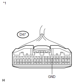
(b) Measure the voltage according to the value(s) in the table below.
Standard Voltage:
|
Tester Connection |
Condition |
Specified Condition |
|---|---|---|
|
D47-1 (IG+) - D47-14 (GND) |
Ignition switch off |
Below 1 V |
|
D47-1 (IG+) - D47-14 (GND) |
Ignition switch ON |
11 to 14 V |
|
*1 |
Component with harness connected (A/C Amplifier) |
| OK | .gif) |
PROCEED TO NEXT SUSPECTED AREA SHOWN IN PROBLEM SYMPTOMS TABLE |
|
.gif)
|
2. |
CHECK HARNESS AND CONNECTOR (A/C AMPLIFIER - BATTERY) |
|
(a) Disconnect the A/C amplifier connector. |
|

(b) Measure the voltage according to the value(s) in the table below.
Standard Voltage:
|
Tester Connection |
Condition |
Specified Condition |
|---|---|---|
|
D47-1 (IG+) - Body ground |
Ignition switch off |
Below 1 V |
|
D47-1 (IG+) - Body ground |
Ignition switch ON |
11 to 14 V |
|
*1 |
Front view of wire harness connector (to A/C Amplifier) |
| NG | |
REPAIR OR REPLACE HARNESS OR CONNECTOR |
|
|
3. |
CHECK HARNESS AND CONNECTOR (A/C AMPLIFIER - BODY GROUND) |
|
(a) Measure the resistance according to the value(s) in the table below. Standard Resistance:
|
|
| OK | |
REPLACE A/C AMPLIFIER |
| NG | |
REPAIR OR REPLACE HARNESS OR CONNECTOR |
 Blower Motor Circuit
DESCRIPTION
The blower motor is operated by signals from the A/C amplifier. Blower motor
speed signals are transmitted in accordance with changes in the duty ratio.
WIRING DIAGRAM
CAUTION / NOT ...
 Back-up Power Source Circuit
DESCRIPTION
The back-up power source circuit for the A/C amplifier is shown below. Power
is supplied even when the ignition switch is turned off. The power is used for diagnostic
trouble code mem ...
Other materials about Toyota Venza:
Removal
REMOVAL
PROCEDURE
1. REMOVE REAR SEAT HEADREST ASSEMBLY
(a) Press the headrest support button and pull up the rear seat headrest
assembly as shown in the illustration.
2. REMOVE REAR SEAT CENTER ...
Tcm
Components
COMPONENTS
ILLUSTRATION
Removal
REMOVAL
CAUTION / NOTICE / HINT
NOTICE:
If automatic transmission parts are replaced, refer to Parts Replacement Compensation
Table to determine if any additional operations are necessary (See page
). ...
Removal
REMOVAL
CAUTION / NOTICE / HINT
HINT:
Use the same procedure for the LH side and RH side.
The following procedure listed is for the LH side.
PROCEDURE
1. REMOVE FRONT WHEEL
2. DRAIN BRAKE FLUID
NOTICE:
If brake fluid leaks onto any pa ...

0.1262