Toyota Venza: Disassembly
DISASSEMBLY
PROCEDURE
1. REMOVE PROPELLER SHAFT
|
(a) Place matchmarks on both flanges. Text in Illustration
|
|

(b) Remove the 4 nuts, 4 bolts and 4 washers.
2. REMOVE INTERMEDIATE SHAFT
|
(a) Place matchmarks on the intermediate shaft and rear propeller shaft. NOTICE: Do not place matchmarks with a punch. Text in Illustration
|
|

(b) Using a hexagon wrench (6 mm), remove the 6 bolts, 2 washers and intermediate shaft from the rear propeller shaft.
3. REMOVE NO. 1 CENTER SUPPORT BEARING ASSEMBLY
|
(a) Using SST and a hammer, loosen the staked part of the nut. SST: 09930-00010 |
|

|
(b) Using SST to hold the universal joint flange, remove the nut and washer SST: 09330-00021 Text in Illustration
|
|

|
(c) Place matchmarks on the universal joint flange and intermediate shaft. Text in Illustration
|
|

|
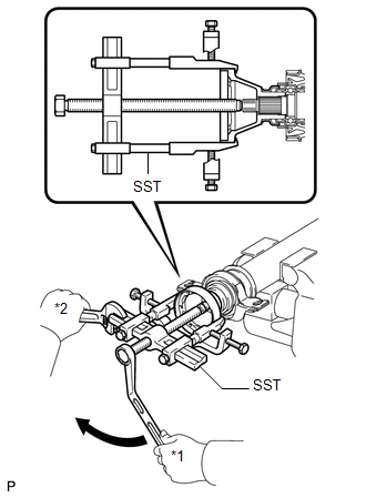
(d) Hold the intermediate shaft in a vise using aluminum plates and remove the universal joint flange using SST. SST: 09950-40011 09951-04020 09952-04010 09953-04030 09954-04010 09955-04061 09957-04010 09958-04011 NOTICE:
|
|

(e) Remove the No. 1 center support bearing assembly and washer.
4. REMOVE NO. 2 CENTER SUPPORT BEARING ASSEMBLY
|
(a) Using SST and a hammer, loosen the staked part of the nut. SST: 09930-00010 |
|

|
(b) Using SST to hold the universal joint flange, remove the nut and washer. SST: 09330-00021 Text in Illustration
|
|

|
(c) Place matchmarks on the universal joint flange and intermediate shaft. Text in Illustration
|
|

|
(d) Hold the intermediate shaft in a vise using aluminum plates and remove the universal joint flange using SST. SST: 09950-40011 09951-04020 09952-04010 09953-04030 09954-04010 09955-04061 09957-04010 09958-04011 NOTICE:
|
|
(e) Remove the No. 2 center support bearing assembly and washer.
 Removal
REMOVAL
PROCEDURE
1. REMOVE TAIL EXHAUST PIPE ASSEMBLY (for 1AR-FE)
2. REMOVE TAIL EXHAUST PIPE ASSEMBLY (for 2GR-FE)
3. REMOVE CENTER EXHAUST PIPE ASSEMBLY (for 1AR-FE)
4. REMOVE CENTER ...
 Inspection
INSPECTION
PROCEDURE
1. INSPECT UNIVERSAL JOINT SPIDER ASSEMBLY
(a) Check the spider bearing axial play by turning the flange while holding
the shaft tightly.
HINT:
If necessar ...
Other materials about Toyota Venza:
Internal Control Module A/D Processing Performance (P060B)
MONITOR DESCRIPTION
This DTC is stored when a communication error occurs in the ECM.
DTC Code
DTC Detection Condition
Trouble Area
P060B
There is an ECM main CPU communication error (1 trip detecti ...
Voice Recognition Microphone Disconnected (B1579)
DESCRIPTION
The navigation receiver assembly and inner rear view mirror assembly (amplifier
microphone assembly) are connected to each other using the microphone connection
detection signal lines.
This DTC is stored when a microphone connection detection ...
No Signal from Transmitter ID1 (C2121/21-C2124/24,C2181/81-C2184/84)
DESCRIPTION
The tire pressure warning valve and transmitter installed in each tire and wheel
assembly measures the tire pressures. The measured values are transmitted as radio
waves to the tire pressure warning antenna and receiver on the body and then se ...

0.1496