Toyota Venza: Disassembly
DISASSEMBLY
PROCEDURE
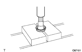
1. REMOVE FRONT DRIVE SHAFT HOLE SNAP RING (for LH Side)
|
(a) Using a screwdriver, remove the front drive shaft hole snap ring. |
|

2. REMOVE NO. 2 FRONT AXLE INBOARD JOINT BOOT CLAMP (for 1AR-FE)
|
(a) Using needle-nose pliers, disengage the 2 claws to remove the No. 2 front axle inboard joint boot clamp as shown in the illustration. |
|

3. REMOVE NO. 2 FRONT AXLE INBOARD JOINT BOOT CLAMP (for 2GR-FE)
|
(a) Using pliers, remove the No. 2 front axle inboard joint boot clamp as shown in the illustration. |
|

4. REMOVE FRONT AXLE INBOARD JOINT BOOT CLAMP
(a) Remove the front axle inboard joint boot clamp.
HINT:
Perform the same procedure as for the No. 2 front axle inboard joint boot clamp (for 2GR-FE).
5. SEPARATE FRONT AXLE INBOARD JOINT BOOT
(a) Separate the front axle inboard joint boot from the inboard joint assembly.
6. REMOVE FRONT DRIVE INBOARD JOINT ASSEMBLY
(a) Remove the grease from the inboard joint assembly.
|
(b) Put matchmarks on the front drive inboard joint assembly and front drive outboard joint shaft assembly. Text in Illustration
NOTICE: Do not use a punch for the marks. |
|

(c) Remove the front drive inboard joint assembly from the front drive outboard joint shaft assembly.
|
(d) Using a snap ring expander, remove the shaft snap ring. |
|

|
(e) Put matchmarks on the outboard joint shaft and tripod joint. Text in Illustration
NOTICE: Do not use a punch for the marks. |
|

(f) Using a brass bar and a hammer, remove the tripod joint from the front drive outboard joint shaft assembly.
NOTICE:
Do not tap the roller.
7. REMOVE FRONT AXLE INBOARD JOINT BOOT
(a) Remove the front axle inboard joint boot from the front drive outboard joint shaft assembly.
8. REMOVE FRONT DRIVE SHAFT DAMPER (w/ 1 Clamp)
|
(a) Using pliers, separate the front drive shaft damper clamp as shown in the illustration. |
|

(b) Remove the front drive shaft damper and front drive shaft damper clamp.
9. REMOVE FRONT DRIVE SHAFT DAMPER (w/ 2 Clamps)
|
(a) Using needle-nose pliers, separate the 2 front drive shaft damper clamps as shown in the illustration. |
|

(b) Remove the front drive shaft damper and 2 front drive shaft damper clamps.
10. REMOVE NO. 2 FRONT AXLE OUTBOARD JOINT BOOT CLAMP
|
(a) Using pliers, remove the No. 2 front axle outboard joint boot clamp as shown in the illustration. |
|

11. REMOVE FRONT AXLE OUTBOARD JOINT BOOT CLAMP
(a) Remove the front axle outboard joint boot clamp.
HINT:
Perform the same procedure as for the No. 2 front axle outboard joint boot clamp.
12. REMOVE FRONT AXLE OUTBOARD JOINT BOOT
(a) Remove the front axle outboard joint boot from the front drive outboard joint shaft assembly.
(b) Remove the grease from the front drive outboard joint.
13. REMOVE FRONT DRIVE SHAFT DUST COVER LH (for LH Side)
|
(a) Using SST and a press, remove the front drive shaft dust cover LH. SST: 09950-00020 NOTICE: Be careful not to drop the inboard joint assembly. |
|

14. REMOVE FRONT DRIVE SHAFT DUST COVER RH (for 2WD RH Side)
|
(a) Using a press, remove the front drive shaft dust cover RH. NOTICE: Be careful not to drop the inboard joint assembly. |
|
15. REMOVE FRONT DRIVE SHAFT DUST COVER (for 2WD RH Side)
|
(a) Using SST and a press, remove the front drive shaft dust cover. SST: 09950-00020 NOTICE: Be careful not to drop the inboard joint assembly. |
|

16. REMOVE FRONT DRIVE SHAFT BEARING (for RH Side)
|
(a) Using a snap ring expander, remove the drive shaft hole snap ring. |
|

|
(b) Using SST and a press, remove the front drive shaft bearing. SST: 09527-10011 NOTICE: Be careful not to drop the inboard joint assembly. |
|

17. REMOVE BEARING BRACKET HOLE SNAP RING (for RH Side)
(a) Remove the bearing bracket hole snap ring.
 Removal
REMOVAL
CAUTION / NOTICE / HINT
HINT:
Use the same procedure for the RH side and LH side.
The procedure listed below is for the LH side.
PROCEDURE
1. PRECAUTION
HINT:
See page ...
 Inspection
INSPECTION
PROCEDURE
1. INSPECT FRONT DRIVE SHAFT ASSEMBLY
(a) Check whether the drive shaft dimensions are within the following
specifications.
Text in Illustration
...
Other materials about Toyota Venza:
Pressure Control Solenoid "G" Electrical (Shift Solenoid Valve SL4) (P2810)
DESCRIPTION
Changing from 1st to 6th is performed by the TCM turning shift solenoid valves
SL1, SL2, SL3, SL4 and SL on and off. If an open or short circuit occurs in any
of the shift solenoid valves, the TCM controls the remaining normal shift solenoid
...
Disassembly
DISASSEMBLY
PROCEDURE
1. INSPECT FRONT OIL PUMP AND GEAR BODY SUB-ASSEMBLY
2. REMOVE STATOR SHAFT ASSEMBLY
(a) Using a "TORX" wrench (T30), remove the 16 bolts and stator shaft
assembly from the oil pump body.
NOTICE:
Keep ...
Removal
REMOVAL
CAUTION / NOTICE / HINT
HINT:
Use the same procedure for the RH side and LH side.
The procedure listed below is for the LH side.
PROCEDURE
1. DISCONNECT CABLE FROM NEGATIVE BATTERY TERMINAL
CAUTION:
Wait at least 90 seconds aft ...

0.1269