Toyota Venza: Diagnosis Circuit
DESCRIPTION
This circuit is used to read the DTCs that are output from the transponder key ECU assembly with the Techstream.
WIRING DIAGRAM

CAUTION / NOTICE / HINT
NOTICE:
If the transponder key ECU assembly is replaced, register the key and ECU communication
ID (See page .gif) ).
).
PROCEDURE
|
1. |
CHECK HARNESS AND CONNECTOR (DLC3 - TRANSPONDER KEY ECU AND BODY GROUND) |
|
(a) Disconnect the transponder key ECU assembly connector. |
|
(b) Measure the resistance according to the value(s) in the table below.
Standard Resistance:
|
Tester Connection |
Condition |
Specified Condition |
|---|---|---|
|
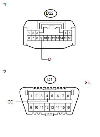
D22-9 (D) - D1-7 (SIL) |
Always |
Below 1 Ω |
|
D1-4 (CG) - Body ground |
Always |
Below 1 Ω |
|
D22-9 (D) - Body ground |
Always |
10 kΩ or higher |
|
D1-7 (SIL)- Body ground |
Always |
10 kΩ or higher |
|
*1 |
Front view of wire harness connector (to Transponder Key ECU Assembly) |
|
*2 |
Front view of wire harness connector (to DLC3) |
| OK | .gif) |
REPLACE TRANSPONDER KEY ECU ASSEMBLY |
| NG | |
REPAIR OR REPLACE HARNESS OR CONNECTOR |
 ECU Power Source Circuit
DESCRIPTION
This circuit provides power to operate the transponder key ECU assembly.
WIRING DIAGRAM
CAUTION / NOTICE / HINT
NOTICE:
If the transponder key ECU assembly is replaced, register the ...

Other materials about Toyota Venza:
Inspection
INSPECTION
PROCEDURE
1. INSPECT EVAPORATOR TEMPERATURE SENSOR
(a) Measure the resistance according to the value(s) in the table below.
Standard Resistance:
Tester Connection
Condition
Specified Condition
...
Using the automatic mode
Press
.
The air conditioning system will begin to operate. In outside air or recirculated
air mode, air outlets, fan speed and air conditioning on/ off are automatically
adjusted according to the temperature setting.
“AUTO” will be displayed on th ...
Problem Symptoms Table
PROBLEM SYMPTOMS TABLE
HINT:
Use the table below to help determine the cause of problem symptoms.
If multiple suspected areas are listed, the potential causes of the symptoms
are listed in order of probability in the "Suspected Area" ...

0.1599